Neonixie IV-9 Numitron Clock


The clock is in production and can be purchased Here!

Table Of Contents

Circuit description

This clock contains six IV-9 Soviet Era Numitron tubes driven by Texas Instruments TPIC6C595N shift register/driver ICs. The clock can be controlled by several different models of Wifi enabled ESP32 microcontrollers. Pinouts are provided for original "DevkitC" boards from Espressif, Adafruit QY Py ESP32 and Seeed Studio XIAO ESP32 series of boards. A logic level shift IC is provided for interfacing the ESP32 to the driver ICs.

Technical Details

- The power input DC jack is 2.1mm(ID) x 5.5mm(OD) in size. Polarity is center positive. Improper polarity will damage the clock!
- Power usage varies with tube current and number of segments lit. Maximum is approx 1-1.2A with an average running current about 600-700mA.
- A REGULATED 5.0v DC adapter is recommended in the 1.2-1.5A range. DO NOT USE UNREGULATED ADAPTERS.
- Your DC adapter should have short, overvoltage and overcurrent protection. A 1350mA self resetting polyfuse is provided on board for additional protection (F1).
- Through-hole connections for alternate power input is provided just below F1 and is fused by F1.
- Ground, 5.0v and 3.3v is provided by several points at the center of the PCB. 3.3v is provided by the ESP controller and draw should be limited within the capacbilities of the controller used.
- All solid capacitor design. No electrolytic capcitors to dry out!

Back to Table of Contents

Assembly instructions

- DC jack, J1
- Polyfuse, F1
- Capacitor, C1, WATCH POLARITY! The blue line on the capacitor indicates the negative pin, match this with the negative pin indicated by the solid white silkscreen on the PCB
- IC1-6, TPIC6C595N, correctly orient part per silkscreen, match the notch on the IC with the notch on the PCB
- IC7, SN74AHCT125N, correctly orient part per silkscreen, match the notch on the IC with the notch on the PCB
- C2-C8, 0.1uf ceramic capacitors
- Optional D1, RL153, slighly larger of the two diodes, correctly orient part per silkscreen. This diode is optional OR bridge the solder jumper on bottom of PCB below diode. A diode is provided for those wishing to drop the voltage to the segments using the diode. We recommend soldering the bridge (bypassing the diode) and use 165 in the brightness setting (PWM) for a segment current of approx 20mA. If you wish to use the diode in circuit, we recommend a brightness setting of 195. See Segment Current section for more details.
- D2, 1N5817, smaller of the two diodes, correctly orient part per silkscreen.
- Install header sockets: H1 and H2 for ESP32 module or the smaller inner 7 pin headers (noted by silkscreen surround) for Adafruit QT Py or Xiao modules.
- Install tubes. Tubes should be mounted with spacing between the glass of the tube and the board. Tubes can be installed on either the top (silkscreen) side of the board or the bottom as desired. The firmware has a configuration setting to switch which side the tubes are on, default is the top or silkscreen side. Note that the PCB has an extra through-hole to allow tube mounting on both sides, one through-hole will always be empty, see this diagram for details.
- Optional: Install incandescent bulbs as colon seperators between minute and second tubes and minute and hour tubes. The bulbs are small and leads can short easily, a short will not cause damage to the board or drivers because of the series resistor in line with the bulb, but you can optionally sleeve one of the leads of the bulb with the included teflon sleeve or use clear enamel or a similar coating to insulate the wires. If colons are used also install resistor R1 and R2, 100 ohms. You must also bridge two solder jumpers on the bottom of the board for the colon bulbs to operate, see the following diagram here.
- Install ESP module on socket

On the first powerup the ESP module will boot up in AP mode. Connect to it at SSID: iv9clock Password: neonixie.com
Goto "Configure new AP", select your wifi, enter it's passphrase and hit "Apply". The ESP will try to connect to your wifi network
The firmware is based on our Z57xM6DV2 nixie clock of which details can be found here.

Back to Table of Contents

ESP32 Software

ESP32 Quick Start

It is recommended to setup this device using a tablet or smartphone.
- When initially powered up the ESP will do a short lamp test and go into "AP"/"Access Point" mode for configuration.
- Lamp test will stop at digit 9 if wifi has not yet been configured. You must complete the configuration process within 5 minutes, as the clock restarts every 5 minutes in this mode.
- To configure the clock connect to the Wifi SSID of "iv9clock" with a password of "neonixie.com"
- Once connected your device should prompt you to configure the clock via it's webpage. A page titled "AutoConnect" should load.
- If not already loaded, click on the menu on the right hand side and select "Configure new AP".
- Select your access point from the list, enter your password and hit apply.
- Your clock will now connect to this access point.

Operating details

When first powered up the clock will go through a lamp test, then attempt to connect to the configured wifi. If sucessful, it will momentarily display the first two decimal numbers of it's IP address, briefly pause, and then display the last two deicmal numbers. For example if your network is 192.168.0.150 the clock will display 192168 and 000150. You can access this IP address through a web browser for further configuration. The configured wifi access point, credentials and configuration options of the clock are maintained in non-volatile memory in the controller.
The clock will revert to "AP" configuration mode if it is unable to connect to the configured access point after about 30 seconds (0.91 BETA3 and above). If unable to connect or if no wifi access points are configured the clock will restart approx every 5 minutes for a retry.

ESP32 Firmware

Firmware for the ESP32 is written in the Arduino IDE with ESP32 extensions. Current shipping firmware is version 0.92 BETA2, firmware with source code is available for download here. Link to changelog.
Older firmware 0.92 BETA1 is available here.

The device has web based firmware update capability. On the main web page of the clock click on "configure settings" then "Update" in the menu. Username = "iv9clock" password = "neonixie.com"
Select the appropriate IV9-ESP32-sourcecode.ino.bin file and hit the update button.

Over The Air, or OTA updates are available after initial flashing of the firmware. The name of the device is "iv9clock-[last-two-octets-of-MAC]" where MAC is the MAC address of the wifi interface. Password for OTA updates is "neonixie.com". OTA updates can be done throught the Arduino framework or using espota.exe / espota.py standalone programs

ESP32 Software Features

Features of ESP32 software as of version 0.92 BETA2 UNIVERSAL
- NTP time and date update with automatic daylight savings time
- PWM brightness adjustment including user controlled timed dimming (v0.92 BETA2)
- LUX meter brightness adjustment, optional module
- Digit cross fading (v0.92 BETA2)
- Temperture / humidity display, optional module
- Date display
- Selectable 12/24 hour display with leading zero blanking options
- Alarm feature (using an optional user installed piezo/speaker element) with music capabilities using RTTTL ringtones (v0.92 BETA2)
- Alternate display options: Altimeter (with optional BMP280 sensor), RSSI, LUX (with optional AHT20 sensor)
- MQTT client to publish sensor data and set clock brightness (v0.92 BETA2)
- "Keep warm" feature to extend tube life. Supplies a small current to unlit segments to keep them warm and lower inrush current (v0.92 BETA2)

Back to Table of Contents

More technical details

Segment "Keep Warm" feature

This feature supplies a small current to unlit segments to keep them warm and lower inrush current. This will help extend tube life. This feature is controlled by the "Segment keep-warm ratio 1/x" in the "Clock Config Advanced" page. Default setting is "10" or a 1/10 duty cycle ratio. A setting of 0 disables this feature.

Segment Current

Measuring segment current may not be convenient on a built clock, this chart is provided to cross reference segment current vs voltage, which is easier to measure. Also provided is an estimate on PWN brightness settings vs segment current. Two brightness/PWM columns are povided, one for use with the diode bypassed and one where the diode is in curcuit.

Segment Current vs Voltage vs PWM
Segment mA Segment Voltage PWM no diode PWM with diode
15 1.90 100 121
16 2.13 113 135
17 2.39 126 153
17.8 2.58 - 165(1)
18 2.63 140 170
19 2.90 153 185
20 3.15 165(1) 195(2)
21 3.43 183 220
22 3.74 200 240
23 4.00 215 255
24 4.35 233 -
25 4.66 250 -
25.5 4.78 255 -
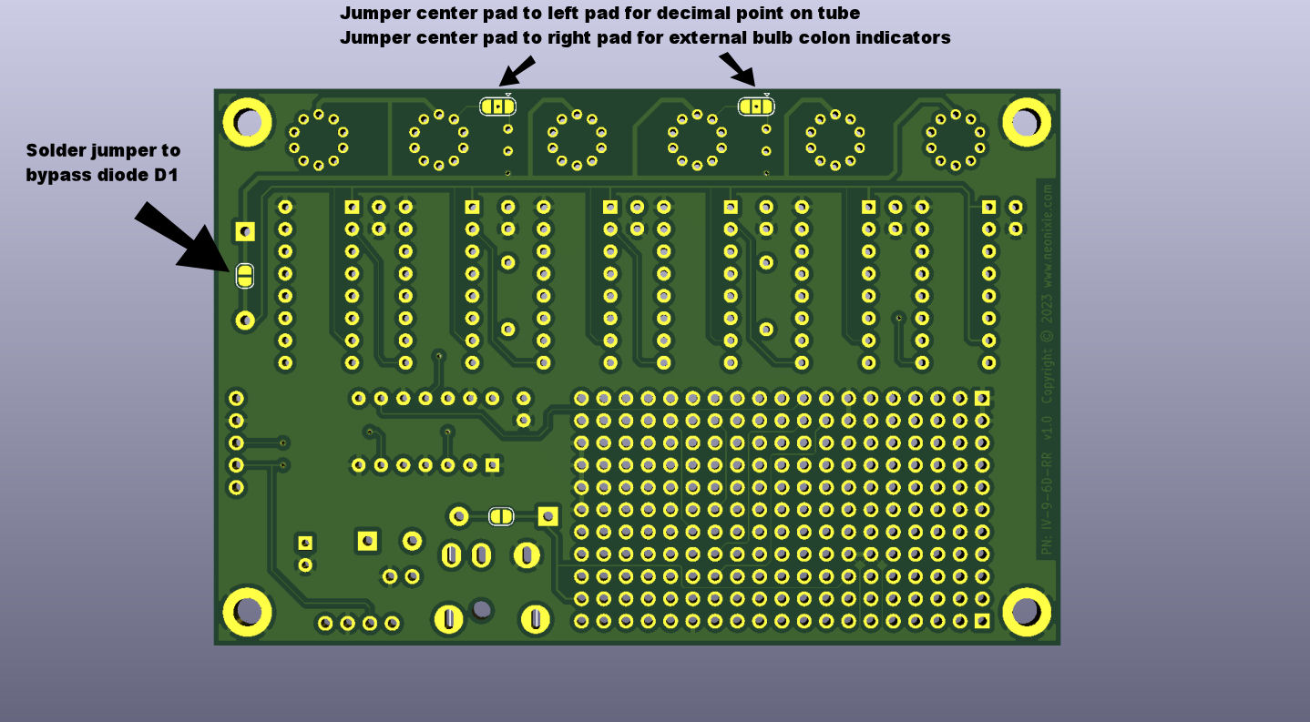
(1)Software default 165, recommended brightness setting, diode bypassed
(2)Recommended brightness setting, with diode 195

Back to Table of Contents

Check this page for more updates as production nears. Thank you for your support!
===============

For those curious about the quote printed on the PC Board..

He was always the cheeriest man in the room, despite fate confining him to a wheelchair for most of his life. Forever with a laugh and smile.
He taught me that in between all of life's tragedies, there are indeed bits of happiness to be found, best enjoyed with good company and little bit of scotch.
His usual parting words as he headed home, loudly to everyone, was.. "LOVE YOU MAN!!!"
He passed away shortly after Thanksgiving 2022.

This clock is dedicated to Rick Richmond, Father, Brother and good Friend.

We all miss you Rick.. Love you man!!!